 Made in the USA
Installation, Operation and Maintenance Instructions Two-Stage Models
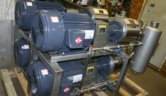
All the INSTALLATION, OPERATION AND MAINTENANCE INSTRUCTIONS for Single-Stage pumps also apply to the Two-Stage models. Since Lyco, Two-Stage models include two pumps piped in series, there are some piping differences, and they are described below.
Service liquid line: It is normally attached to the first stage pump in the series in the same way as with the “STRAIGHT THROUGH” arrangement shown on page 7. Service liquid to the second stage pump comes from the first pump through the interconnecting piping (from the exhaust port of the first to the vacuum port of the second).
High vacuum performance can often be improved with greater service liquid flow than the standard 2-3 gpm; however, this may cause cavitation in some models. Cavitation may also occur if the inlet is blocked off or if there is unusually large quantities of liquid entering the pump package from the process. Cavitation reduces performance and puts stress on pump rotors, shafts, bearings and motors and produces a noise which sounds like nuts, bolts and screws violently rattling around inside the pump. This cavitation can be eliminated. As explained below.
Drain piping: Cavitation can be eliminated by bleeding air into the pump and or relieving some of the service liquid from the drain of the first stage pump and piping it into the recirculation inlet of the second stage pump. This piping, along with a hand valve, is factory installed on those models which have potential for cavitation. At initial start up, allow the pump to reach desired vacuum with the hand valve closed. Then, slowly open the valve until cavitation is tuned out, and the best performance obtained. This can be a permanent setting.
This drain piping can also be used to relieve unusually large quantities of liquid entering the pump package from the process. The second pump can also have a similar drain piping, which discharges directly into the separator/muffler, if this is needed to reduce the motor load on the second pump caused by excessive liquid. The valve on the second pump should also be tuned for optimum performance.
Vacuum and exhaust lines: The vacuum line from the process is attached to the inlet port of the first stage pump. Exhaust from this pump is piped to the inlet port of the second stage pump, which is exhausted into the separator/muffler. In some models where the first pump is much larger than the second, a bypass check valve is provided to allow the first pump to also exhaust into the separator/muffler during pump down. This allows higher pump down CFM and reduces motor load during the early stages of pump down on these models. When the vacuum reaches 15-20"Hg, the check valve closes, and the package operates as a complete Two-Stage system.
Lyco pumps are designed to be easy to field repair. They can be readily disassembled and reassembled without the need to reset clearances between the rotor and the porting plate if you follow instructions starting on page 13. The main point is “DONʼT TOUCH THE TWO ADJUSTING SETSCREWS (31).”